Evaluation Dialog DRM
|
The Evaluation Dialog provides detailed information about the current DRM
reception. Some
measurements and
parameters as well as some
plots can be viewed here. Furthermore
advanced settings can be done. |
 |
 |
Measurements
|
DC Frequency Offset |
This is the estimation of the DC frequency offset. This offset corresponds
to the resulting sound card intermedia frequency of the front-end. This
frequency is not restricted to a certain value. The only restriction
is that the DRM spectrum must be completely inside the bandwidth of
the sound card. |
|
Sample Frequency Offset |
This is the estimation of the sample rate offset between the sound
card sample rate of the local computer and the sample rate of the D
/ A (digital to analog) converter in the transmitter. Usually the sample
rate offset is very constant for a given sound card. Therefore it is
useful to inform the Dream software about this value at application
startup to increase the acquisition speed and reliability. |
|
Doppler / Delay |
The Doppler frequency of the channel is estimated for the Wiener
filter design of channel estimation in time direction. If linear interpolation
is set for channel estimation in time direction, this estimation is
not updated. The Doppler frequency is an indication of how fast the
channel varies with time. The higher the frequency, the faster the channel
changes are.
The total delay time of the Power Delay Spectrum (PDS) is estimated
from the impulse response estimation derived from the channel estimation.
This delay corresponds to the range between the two vertical dashed
black lines in the Impulse Response
(IR) plot. |
|
I/O Interface LED |
This LED shows the current status of the sound card interface. The
yellow light shows that the audio output was corrected. Since the sample
rate of the transmitter and local computer are different, from time
to time the audio buffers will overflow or under run and a correction
is necessary. When a correction occurs, a "click" sound can be heard.
The red light shows that a buffer was lost in the sound card input stream.
This can happen if a thread with a higher priority is at 100% and the
Dream software cannot read the provided blocks fast enough. In this
case the Dream software will instantly loose the synchronization and
has to re-synchronize. Another reason for red light is that the processor
is to slow for running the Dream software. |
|
Time Sync Acq LED |
This LED shows the state of the timing acquisition (search for the
beginning of an OFDM symbol). If the acquisition is done, this LED will
stay green. |
|
Frame Sync LED |
The DRM frame synchronization status is shown with this LED. This
LED is also only active during acquisition state of the Dream receiver.
In tracking mode this LED is always green. |
|
FAC CRC LED |
This LED shows the Cyclic Redundancy Check (CRC) of the Fast Access
Channel (FAC) of DRM. FAC is one of the three logical channels and is
always modulated with a 4-QAM. If the FAC CRC check was successful,
the receiver changes to tracking mode. The FAC LED is the indication
whether the receiver is synchronized to a DRM transmission or not. |
|
SDC CRC LED |
This LED shows the CRC check result of the Service Description Channel
(SDC) which is one logical channel of the DRM stream. This data is transmitted
in approx. 1 second intervals and contains information about station
label, audio and data format etc. The error protection is normally lower
than the protection of the FAC. Therefore this LED will turn to red
earlier than the FAC LED in general. |
|
MSC CRC LED |
This LED shows the status of the Main Service Channel (MSC). This
channel contains the actual audio and data bits. The LED shows the CRC
check of the AAC core decoder. The SBR has a separate CRC, but this
status is not shown with this LED. If SBR CRC is wrong but the AAC CRC
is ok one can still hear something (of course, the high frequencies
are not there in this case). If this LED turns red, interruptions of
the audio are heard. The yellow light shows that only one 40 ms audio
frame CRC was wrong. This causes usually no hearable artifacts. |
|
|
|
Parameters
|
DRM Mode / Bandwidth |
In a DRM system, four possible robustness modes are defined to adapt
the system to different channel conditions. According to the DRM standard:
- Mode A: Gaussian channels, with minor fading
- Mode B: Time and frequency selective channels, with longer
delay spread
- Mode C: As robustness mode B, but with higher Doppler spread
- Mode D: As robustness mode B, but with severe delay and
Doppler spread
The bandwidth is the gross bandwidth of the current DRM signal. |
|
Interleaver Depth |
The symbol interleaver depth can be either short (approx. 400 ms)
or long (approx. 2 s). The longer the interleaver the better the channel
decoder can correct errors from slow fading signals. But the longer
the interleaver length the longer the delay until audio can be heard
(after a re-synchronization). |
|
SDC / MSC Mode |
Shows the modulation type of the SDC and MSC channel. For the MSC
channel, some hierarchical modes are defined which can provide a very
strong protected service channel. |
|
Prot. Level (B/A) |
The error protection level of the channel coder. For 64-QAM, there
are four protection levels defined in the DRM standard. Protection level
0 has the highest protection whereas level 3 has the lowest protection.
The letters A and B are the names of the higher and lower protected
parts of a DRM block when Unequal Error Protection (UEP) is used. If
Equal Error Protection (EEP) is used, only the protection level of part
B is valid. |
|
Number of Services |
This shows the number of audio and data services transmitted in
the DRM stream. The maximum number of streams is four. |
|
Received time - date |
This label shows the received time and date in UTC. This information
is carried in the SDC channel. |
|
|
|
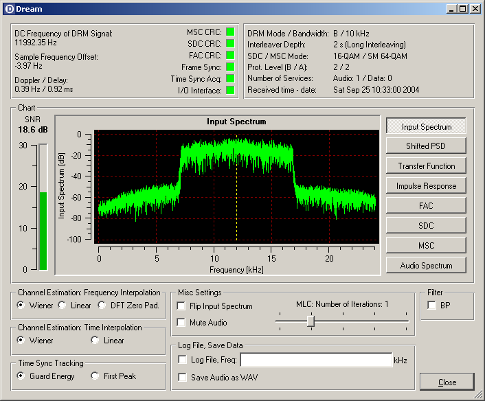
Chart
| SNR |
Signal to Noise Ratio (SNR) estimation is plotted as a bar and as
a value. |
|
Main Plot |
Graphical display of different vectors of the DRM decoder.
For more information click
here! |
|
|
|
Advanced Settings
|
Frequency Interpolation |
With these settings the channel estimation method in frequency direction
can be selected. The default value uses the most powerful algorithm.
Wiener (default) - Wiener interpolation uses estimation
of the statistics of the channel to design an optimal filter for noise
reduction.
Linear - Simple linear interpolation method to get the channel
estimate. The real and imaginary parts of the estimated channel at the
pilot positions are linearly interpolated. This algorithm causes the
lowest CPU load but performs much worse than the Wiener interpolation
at low SNR's.
DFT Zero Pad: - Channel estimation method for the frequency direction
using Discrete Fourier Transformation (DFT) to transform the channel
estimation at the pilot positions to the time domain. A zero padding
is applied to get a higher resolution in the frequency domain -> estimates
at the data cells. This algorithm is very speed efficient but has problems
at the edges of the OFDM spectrum due to the leakage effect. |
|
Time Interpolation |
With these settings the channel estimation method in time direction
can be selected. The default value uses the most powerful algorithm.
Wiener (default) - Wiener interpolation uses estimation
of the statistics of the channel to design an optimal filter for noise
reduction.
Linear - Simple linear interpolation method to get the channel
estimate. The real and imaginary parts of the estimated channel at the
pilot positions are interpolated linearly. This algorithm causes the
lowest CPU load and the audio is decoded more quickly, but in general
it performs worse than the Wiener interpolation especially at low SNR's. |
|
Time Sync Tracking |
With these settings the time synchronization tracking methods can
be selected.
Guard Energy (default) - This algorithm utilizes the estimation
of the impulse response and tries to maximize the energy in the guard-interval
to set the correct timing.
First Peak - This algorithm searches for the first peak in the
estimated impulse response and moves this peak to the beginning of the
guard-interval (timing tracking algorithm). |
|
Flip Input Spectrum |
Checking this box will flip or invert the input spectrum. This is
necessary if the mixer in the front-end uses the lower side band. |
|
Mute Audio |
The audio can be muted by checking this box. The reaction of checking
or unchecking this box is delayed by approx. 1 second due to the audio
buffers. |
| MLC,
Number of Iterations |
In DRM a multilevel channel coder is used. With this code it is
possible to iterate the decoding process in the decoder to improve the
decoding result. The more iterations are used the better the result
will be. But switching to more iterations will increase the CPU load.
Simulations showed that the first iteration (number of iterations =
1) gives the most improvement (approx. 1.5 dB at a BER of 10-4 on a
Gaussian channel, Mode A, 10 kHz bandwidth). The improvement of the
second iteration (number of iterations = 2) will be as small as 0.3
dB.
The recommended number of iterations given in the DRM standard is one
iteration (default value: number of iterations = 1).
The selection is saved in the Dream.ini file. |
|
Log File |
Checking this box causes Dream to write two kinds of log files about
the current reception of an audio service using AAC source coding, a
standard and a long log file. Both files are written to the directory
were the Dream application is located.
The standard log file DreamLog.txt is compatible to the
log file created by the "DRM Software Radio". Each minute information
about the average SNR, number of correct decoded FAC and number of correct
decoded MSC blocks is recorded. The header of each log section also
contains frequency, station label, bit-rate, mode and bandwidth. This
file format is read by analyzer software like "DRMcalc"
by Carsten Knütter.
The long log file DreamLogLong.csv includes more detailed
technical information: Frequency, date, time, average SNR, status of
synchronization, status of FAC and MSC decoding, number of transmitted
and decoded audio frames, Doppler frequency and the total delay time
of the Power Delay Spectrum (PDS). It gets updated every second so that
the resulting file size is growing quickly. The CSV file format can
be handled by many spreadsheet applications like Microsoft Excel®
or Sun StarOffice®.
Known limitation: Due to a problem with QT timer implementation under
Windows no Dream window should be moved or re-sized during logging!
This problem does not exist in the Linux version of Dream. |
|
Freq |
In the text field the current selected frequency on the front-end
can be entered. This frequency will be written to the log file and saved
in the Dream.ini file. |
|
Save Audio as WAV |
Save the audio signal as stereo, 16-bit, 48 kHz sample rate PCM
wave file. Checking this box will let the user choose a file name for
the recording. |
|
Filter |
Checking the BP box will activate a band path filter to reduce
interference from adjacent channels. The filter bandwidth is automatically
set to the bandwidth of the current DRM signal.
This filter should only be used in difficult reception situations because
it increases CPU load noticeably. |
|
|
|
|